MASI: Modules for Aerial and Satellite Imagery
Version 6.0 Aerial Modules
Tutorial
|
|
|
|
VisionOnSky
Co., Ltd. |
|
|
www.visiononsky.com |

File
Version: v1.0
March
30, 2023
MASI: Modules for Aerial and Satellite Imagery
Version 6.0 Aerial Modules
Tutorial
|
|
|
|
VisionOnSky
Co., Ltd. |
|
|
www.visiononsky.com |
File
Version: v1.0
March
30, 2023
Special Notes:
(1) Before starting the tour of MASI
software, please be sure that the installation manual and tutorials are fully read and
understood. If users need to know and exploit the software deeply, please
further read user manual of the software.
(2) Users can receive software license through two
manners. One is to download license from internet. If this manner is used,
users should provide us an e-mail address. We send the password to the e-mail
address via the Sense Shield (SS) Licensing platform. If you have not found it,
please check your e-mail trash (spam) box. The e-mail text may be written by
Chinese, but the English string is actually the password. The account used to
log in the SS (Sense Shield) middleware is your e-mail address and the password
is the English string sent to your e-mail box. After you download the software
license and bind it on your machine, you can use the software even though you
disconnect the internet. If the internet connection is not very stable, we recommend
that you disconnect the internet, otherwise a timeout error may happen. Using
this manner, users can download software package, tutorials, user manuals,
installation manual, etc. from website: http://www.visiononsky.com. The other
manner is to use a physical dongle to get the software license which is stored
in this dongle. You don’t need to provide us an e-mail address and don’t need
to log in in the SS middleware, just need to plug the dongle on computer. But
you still need to install the SS middleware. Using this manner, users should
contact us to get the software package and the package downloaded from the
website is invalid for the physical dongle.
(3) The file name
and the path name to be used in English version of MASI software should be
English characters, and the file name and the path name can
not include blank space.
(4) The full
path of file can not be too long (e.g., more than 200
characters). If it is too long, please shorten the full path of file.
(5) Please make
sure that there is enough free space in the disk where the work directory is
located.
(6) If text
editing is needed, editors such as UltraEdit, NotePad++ are highly recommended.
(7) Because of
the update of software version, some GUI interfaces of programs illustrated in
this tutorial are not the newest, which are changed and adjusted. The latest
user manual of the software provides the newest one, please refer to that
document.
(8) Any feedbacks,
suggestions, and problems, please send to the e-mail address:
jhyang@vip.163.com
History of Versions
Version 1.0: finishing the first
version of this document, tutorial of aerial modules. Time: Mar. 2023, Author: VisionOnSky Co., Ltd.
1 The brief introduction of aerial modules of MASI
Version 6.0
The functions in MASI Version 6.0 for
aerial images can be packaged as some relatively independent modules. The
modules include the following functions: automatic stereo matching and
generation of highly dense DSM (as well as point clouds), automatic 3D
modeling with true
color textures, automatic true ortho-rectification,
automatically transforming DSM to DTM (the height difference between DSM and
DTM is the height of building / tree), automatic finding change of surface
height (used
in the automatic finding of new buildings, the unplanned buildings and the
removed buildings, and estimating their corresponding accurate height),
automatic mosaic
(mosaic of DSMs, mosaic of ortho-rectified images, mosaic
of histogram matched images), volume
calculation, extraction of building attributes (the center position of building,
height of building, number of layers, area of ground, and construction area of
building), image displaying, interactive editing of DSM/DEM, collecting
polygons, and
some commonly used tools. These modules for aerial images are
shown to users by a main interface (aerialMain.exe). After installing of MASI
software, users can launch the main interface by clicking the shortcut to aerialMain.exe
or directly double-clicking the program, aerialMain.exe, itself. Then, the
corresponding functions can be launched by clicking the icons in the
interfaces.

Figure 1. The main interface (aerialMain.exe) of
aerial modules
The features of aerial modules in MASI
Version 6.0 are as follows:
(1) Supporting all aerial digital
cameras with the form of frame, traditional optical aerial camera, and
calibrated consuming camera. Almost all frame cameras are supported, such as
DMC I/II/III, UCD, UCX, UltraCam Falcon, UltraCam Eagle, UltraCam Eagle M series,
SWDC-2 and SWDC-4 produced in China, middle-frame aerial camera, RCD 30, PhaseOne, Hasselblad as well as traditional optical film
camera.
(2) GUI
operating manner and batch processing manner are
supported in MASI software. Only one push of button is needed to carry out DSM
generation and ortho-rectification of an aerial
block. User can also write batch files including commands to fulfill the pipeline
processing for a specific procedure. Distributed computing where multiple tasks
can be allocated to multiple machines is also supported.
(3) Modules
demanding large computation requirements, such as automatic stereo matching and DSM
generation, and mosaicking, have capability of
parallel computing. Thus, the computational resources can be fully exploited.
(4) Supporting
different operating systems, either Windows OS or Linux OS. MASI can run on the
commonly used PC computer, and cluster computer usually located in data center
or supercomputer center. This tutorial is based on Windows OS. If you need the
document of usage of MASI on Linux OS, please contact us.
For more details
about functional features and technique traits, please refer to the document of
Product Descriptions and Typical Applied Cases.
2 The automatic
processing flowchart for aerial image
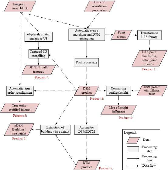
Figure 2. The automatic processing
flowchart for aerial image
Currently in MASI
Version 6.0 there is not a function of aero-triangulation for aerial images,
but the results of aero-triangulation from mainstream software can be used in
MASI software. Experimental results show that the results of aero-triangulation
from Inpho, PhotoMOD, PATB,
Bingo, BLUH, PixelGrid, and Geolord_AT
can be used in MASI software.
In the flowchart, each step corresponds to a function
in aerial modules as follows:
(1) Automatic stereo matching
and DSM generation. According to the lists of
exterior elements of images in an aerial block, the program fulfills stereo
matching for all stereo pairs and generates dense point clouds for each stereo
pair (users can decide whether the text-formatted point clouds files with
extension .xyz are saved by setting the configuration option; in this file each
line is for one point). Then, these point clouds are transformed to DSMs and
these DSMs are mosaicked. At last, a mosaicked DSM covering the whole aerial
block is generated (the DSM before interpolation). Clicking the icon showing “DSM”
in the main interface,

The following
menu will pop up.

The command item, Easily used Model, in the menu is to call the function of
stereo matching and DSM generation. After processing, a
mosaicked DSM (the DSM before interpolation) is generated. The program not only
supports parallel computing of multi-threads and multi-processors provided by a
single machine, but also has the ability to distribute all images of the whole
block to multiple machines evenly. Users can also adopt the flexibly connected model
to generate DSM. It has relatively more steps, but is flexible to connect these
steps, and is able to manually distribute processing tasks to multiple machines.
Using this flexibly connected model, users can interrupt and resume the task at
any time. Usually users who use the flexibly connected model need to know the
software and the principle behind the software more. Recommendations are given
that at the beginning users can choose the easily used method while users who
already have some experiences after a period of time can choose the flexibly
connected method. The description of easily used model is only given in this
this tutorial. For details about flexibly connected model, please refer to user manual.
(2) Post processing for DSM: The above mosaicked
DSM has some
areas which have not height value (before interpolation these areas are filled
by using no-data values). In this step, these areas with no-data value are
interpolated, and outliers (or small spots of
errors) in the resultant DSM after interpolation are removed. The output of this step
is the product of dense DSM, which is generated by this software. The DSM
product can be used in different applications followed (e.g., volume
calculation, finding
change of surface height, extraction of the height of building / tree). The
command item,
Post Processing, in the menu is to call the function of post
processing for DSM.
(3) Automatic true ortho-rectification:
The program uses the DSM source generated in Step 2 to ortho-rectify
all images in an aerial block. For each image, an ortho-rectified
image is generated. These ortho-rectified images are
mosaicked and an ortho-mosaic image covering the whole
aerial block is generated. An alternative way is that DTM as a height source,
which can be from third party or generated by MASI software, is used to ortho-rectify images. This way is more common. Because DSM
generated by MASI software is highly dense and has high quality, we highly
recommend that the highly dense DSM is used to fulfill true ortho-rectification
if the overlapping between images is high (e.g., the flight / side
overlapping ratio is 80/60). Clicking the icon showing “True Ortho” in the main
interface,

The following menu will pop up.

The command item, Aerial
Ortho, in
the above menu is to call the function of ortho-rectification. After processing, an
ortho-mosaicked image is generated.
(4) Comparing
surface height and change finding. By comparing DSMs of different phases
(generated by MASI software), the program can automatically find change of the
surface height and calculate the value of changed height. It can be used in the
automatic finding of new buildings, the unplanned buildings and the removed
buildings, and estimating their corresponding accurate height. The map of
height difference produced in this step can be used in the following extraction
of building attributes (the center position of building, height of building,
number of layers, area of ground, and construction area of building). Clicking
the icon showing “Surface Change” in the main interface,

The operating
interface of the function will be launched.
(5) Automatic
DSM2DTM: The program
deletes the non-grounded objects like buildings, trees in DSM and transforms
DSM to DTM where the pure ground height is saved.
Clicking the icon showing “DSM to DTM” in the main interface,
The operating
interface of the function will be launched.
(6) Height estimation of building / tree. The
height difference between DSM and DTM (nDSM) is the
height of building / tree. The height difference (raster form) produced in this step can
be used in the following extraction of building
attributes (the center position of building, height of building, number of
layers, area of ground, and construction area of building). DSM is generated by
the functions in MASI software (including post processing for DSM), and DTM can
be produced in the step 5 in this flowchart. Clicking the icon showing
“Building height” in the main interface,
The operating
interface of the function will be launched.
(7)
Applications. The generated dense DSM, map of height difference, nDSM
(i.e., height of building / tree) in above steps can be passed to the
application functions which fulfill volume calculation and extraction of
building attributes (the center position of building, height of building,
number of layers, area of ground, and construction area of building). Clicking
the icon showing “App” in the main interface,

The following
menu will pop up.
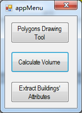
Currently two applications modules are included, i.e.,
volume calculation and automatic extraction of building
attributes in the light of buildings footprints. The command item, Calculate
Volume, in the above menu is to call the function of volume
calculation.
The GUI program called from the command item is calVolumeForm.exe. Also,
the GUI program can be launched by double-clicking the program directly. For more
details, please refer to “Usage of the calVolume.exe and calVolumeForm.exe
programs”. The command item, Extract Buildings’
Attributes, in
the above menu is to call the function of extraction of
building attributes. The GUI program called from the command item is extBldgAttributesForm.exe. Also,
the GUI program can be launched by double-clicking the program directly. For more
details, please refer to “Usage of the extBldgAttributes.exe and
extBldgAttributesForm.exe programs”. In the course of volume calculation and
automatic extraction of building attributes, the bounds in the form of polygon
are needed. Users can click the command item, Polygons Drawing Tool, in above
menu to launch the interactive tool, collectPolygons.exe, to collect polygons
and save them.
(8) 3D modeling
with true
color textures. Images and highly dense DSM
generated in previous steps are used to generate 3D TIN models with true color
textures. The 3D models are in a form of tiled mesh. The data type of the
images which are used for texture mapping is unsigned 8 bit integer. If it is
not, user should stretch the images to unsigned 8 bit using the autoStretch.exe
program provided by MASI software. Clicking the icon showing “Textured 3D Model”
in the main interface,
The following
menu will pop up.

The command item, textured 3D modeling, in the above
menu is to call the function of 3D modeling. The GUI program called
from the command item is aerialScene3DForm.exe. Also, the GUI
program can be launched by double-clicking the program directly. For more
details, please refer to “Usage of the aerialScene3D.exe and aerialScene3DForm.exe programs”.
In addition, other functions are included: image
displaying, interactively
editing of DSM/DEM, collecting polygons, automatic mosaic (mosaic of
DSMs, mosaic of ortho-rectified images, mosaic of histogram
matched images),
transforming RGB image to grey image, rotation of image,
reflection of image, transforming point clouds to surface in the form of
raster, transforming DSM with raster form to point clouds, image cropping,
creating overviews for image.
The method of format transform for point clouds
generated by MASI software: the file of point clouds generated by the software
is text format, which can be transformed to LAS format through the following
steps. In the course of transform, a third party software package OSGeo4W
(including the open source library, i.e., libLAS) is
exploited. The package can be downloaded from the official website of OSGeo4W.
The steps are as follows:
(1) Translation to LAS format: the command, namely
txt2las.exe (OSGeo4W package includes the program), in the open source library,
libLAS, can be used to translate the point clouds
with text format to the LAS file. The corresponding command is as follows:
>txt2las.exe -parse xyz -i filename.xyz
-o filename.las
(2) Assigning RGB values: the command, namely
las2las.exe (OSGeo4W package includes the program), in the open source library,
libLAS, can be used to assign the RGB values from
truly ortho-rectified image to the points in LAS
point clouds file. The colored point clouds are obtained. One example of the
command is as follows:
>las2las.exe
-i points.las --color-source ortho.tif
-o points_rgb.las --file-format 1.2 --point-format 3
--color-source-scale 256 --color-source-bands 1 2 3
3 The flowchart sample of aerial images
In the
following, the flowchart will be illustrated through a sample. First, the main
interface of the aerial modules is launched via the Windows Start menu, i.e.,
calling the program, aerialMain.exe. The launched main interface is as follows:

Clicking the icons in
the main interface is to call the corresponding functions. The main steps of
the flowchart sample are as follows:
Step 1: Automatic stereo matching and DSM generation
Clicking the
icon showing “DSM” in the main interface,
The following
menu will pop up.
By clicking the command item, Easily used Model, in the above menu, the
GUI program is launched. After processing, a
mosaicked DSM (the DSM before interpolation) is generated. The graphical
interface of the program is as follows:

First, all files required in the course
of automatic stereo matching and DSM generation, such as images, the file of interior
parameters of camera, and the list file of exterior elements, are copied to a
directory, e.g., I:\points\images, and set it as work directory. When MASI
graphical interface is used, all required files should be put in the same
directory and the directory is set as work directory.
The file of interior parameters of
camera is interiorfile.dat. The format of file is as follows:

Defining of
each line in the file (the definition of the underlying coordinate system is
outlined in Appendix III of user manual):
Line 1 is the X
coordinate of principal point in image coordinate system;
Line 2 is the Y
coordinate of principal point in image coordinate system;
Line 3 is the X
coordinate (Unit: mm) of principal point in camera coordinate system (the
center of the camera as the original point in the coordinate system);
Line 4 is the Y
coordinate (Unit: mm) of principal point in camera coordinate system (the
center of the camera as the original point in the coordinate system);
Line 5 is the
focal length of the camera (Unit: mm);
Line 6 is the
pixel size of the camera (Unit: mm).
Users can
create a new file of interior parameters of camera and save it by clicking the “new”
button in the interface. The operating form to create a file of interior
parameters is as follows:

Each
item in the form exactly corresponds to the item in the file of interior
parameters of camera. The advantage is to operate easily. Recommendation is
given that at the beginning users utilize the interface of the “new” to create
a file of interior parameters of camera.
The
content of the list file of exterior elements is as follows:

…
Each line corresponds to exterior
elements of an image, and these lines are arranged in sequence. First element
is the image ID which is followed by six exterior elements (Attention:
the first element, image ID, do not include extension of image file).
The contents after the six elements are discarded. The six elements are three
linear elements and three angle elements. The order of these exterior elements
can be either first linear elements then angle
elements, or first angle elements then linear elements. The format of oriList.dat
can also be the output format of PATB software (i.e., the rotation system is
indicated by rotation matrix directly). For more details, please refer to user
manual.
In this case, exterior
elements included in oriList.dat are formulated as follows: first linear
elements then angle elements, omega-phi-kappa rotation system. The
unit of rotational angle is degree. The exterior
elements from different software, such as Inpho, PhotoMOD, PixelGrid, may have different formats in terms of order
between linear and angle elements, rotation system, and the unit of angle,
comparing with this case in the sample. Users should set the provided three
options in the interface (Order of exterior elements, Rotation
system, and Unit of angle), according to the real case of the exterior
elements. The different combination of the values of three options provided in
this software can support almost all formats of exterior elements from the
available aero-triangulation software. For more details, please refer to the
sections of stereo matching and DSM generation for aerial images in user
manual.
Extension of image in the configuration
options means the adopted format of images. It can be TIFF or JPEG, which are
commonly used format for aerial image. The following three options should be
set according to the real case of the exterior elements. In this sample, the
selected values of the three options are shown in the above figure of the
operating interface.
Height limit
has three choices: determined by program, setting maximum and minimum heights
from right side, and selecting third part elevation file (The coordinate system
of elevation file must be the same as that of exterior elements), respectively.
If users choose to set height limit from right side, the maximum and minimum
heights are values of surface height (including height of the man-made objects)
of the highest and lowest points above sea level in the aerial block. The
height value above sea level is based on the adopted coordinates system. The
maximum and minimum height value of elevation can be extended, to some extent,
i.e., increasing the maximum value a little bit and decreasing the minimum
value a little bit.
Rotation or not first: whether image
should be rotated in advance. For some cases, a specific rotation is required:
the layout of image that is used to determine orientation of image is different
from the layout of image which is saved in computer and used as input of the
program. There are four cases: none rotation,
rotation of clockwise 90 degree; rotation of anti-clockwise 90 degree, and
rotation of 180 degree. In this sample, no rotation is needed
in advance. If the exterior elements with PATB
format exported by Inpho software are adopted, the
images before stereo matching may need to be rotated 180 degree because the
directions of coordinates defined in Inpho software
are different. Users can set to rotate images 180 degree via the option.
Format of intermediate files: the
intermediate files are epipolar and disparity images
whose file format can be configured. The formats, such as GTiff
and ERDAS IMAGINE (.img), can be used.
Ratio of image size: the ratio of the
size of original image to the size of matched image. The size of matched image
can be the same as the original image, or can be reduced in the light of some
specific scale. Two cases are supported in the software: 1 means the size of
matched image in each dimension is the same as the original image, while 2
means the size of matched image is the 1/2 size of the original image in each
dimension. Reduction of size in the course of stereo matching can lead to
reduction of computational requirement and of the amount of data, and also
accelerate the process. But it also leads to the loss of precision, decrease of
the density of points. Users can select the value in the light of specific
requirements.
Delete intermediate files or not: users
can determine whether the intermediate files (epipolar
and disparity images) are deleted by setting the option. The epipolar images can be used in the stereo displaying and
further in the line-drawing in the stereo displaying.
Method to select height value: the
method how to select the height value when there are multiple 3D points in a
grid. The software supports three methods: max, min, average, which select
maximum, minimum, average height value, respectively. The recommended method is
max.
Save point
clouds or not: users can determine whether point clouds generated from each
stereo pair are saved as a text-formatted file with extension .xyz. The default
setting is no-saving.
Tiles and overlapped size between
tiles: tiles into which the whole image is divided and overlapped size is the
extended pixels for each tile. 2 means the whole image is divided to 2 tiles
along the image height direction, and in the course of matching each tile is
extended 512 pixels in the two ends. This option is useful for the situation
where the image frame is very large and the memory of used computer is limited.
If the number of tiles is set as 1, the image is not divided.
Partitions and
Part ID: The two parameters are used for distributed computing on multiple
machines. The program, aerialDSM.exe, can equally partition all images of the
whole block into different parts, in the light of the number of used computers.
Each part corresponds to a computer and is identified by a serial number. The
serial number is 0-based and integer type, its range is 0 ~ (Partitions - 1).
For the default setting in this form, partitions are 1, which means only one
computer is used for computation. All images are treated as one part and are
processed on this machine whose part ID is 0. Attention: MASI software need to
be installed on all computers used for computation and it should be ensured
that all used files including images, the list file exterior elements of the
whole block, the file of interior parameters of the camera and the
configuration file are accessed by each machine.
Number of used
threads per processor: setting the number of used threads (CPU cores or the
virtual CPU cores by using hyper-threading technology) per processor. For the
cases where CPU cores are enough, we suggest that number of 4, 6 or 8 is set here.
Bounding
polygon: users can determine whether a bounding polygon is used to limit the region
of stereo matching. After checking the checkbox, a shape format file which
includes a polygon for bounding should be selected. Compared to the region
bounded by the used polygon, the resultant region after the utilization of
bounding polygon in stereo matching may be extended a little bit. The bounding
polygon file can include only one polygon and its coordinate system must be the
same as that of exterior elements. For default setting, bounding polygon is not
used. The button of “Selecting File” in the right side is invalid.
After the above
options in the interface are set, users can click “Save Configuration” to save
these options. These configuration options will be saved in a configuration
file, aerialDSM.conf, and next time the options can
be loaded from the configuration file by clicking “Load Configuration”. The
configuration file, aerialDSM.conf, is also stored in
the work directory. If “Execute” is clicked, the configuration file will also
be generated in the same way.
In the output
setting, users should set the filename of the mosaicked DSM (the DSM before
interpolation), the grid spacing (cell size) of the raster file used to store
height value (the value of grid spacing can not be
better than the actual ground sample distance, GSD, of image), the no-data
value used to fill in the area without height value in the raster DSM file (no-data
value).
Because the
computational requirements for stereo matching are large, the software supports
parallel computing to leverage advances of the multi-core computer. Serial
or parallel processing can be selected. If parallel processing is selected,
number of processors should be inputted as well as the current user name using
the Windows OS and password of the user. Next time users can load the information
by clicking the load button, and do not need input the information again. Users
should be very careful when selecting the number of processors, which should be
determined in the light of the number of available CPU cores in the adopted
machine, the size of physical memory and the size of image frame. There are
three points for selecting the number of processors. First, the product of the
value set in the option, Number of used threads per processor, and the number
of used processors here can not exceed the total
number of CPU cores (or the virtual CPU cores by using hyper-threading
technology). Second, all consumed memory can not
exceed the physical memory on the machine. For the case where an image is
divided into two tiles and then is processed, 8 G - 16 G memory is consumed in
one processor, generally. If tile-dividing is not used, the consumed memory
will be two times. Also, the consumed memory is related to the size of image.
The bigger the size, the more is the memory consumed. The total number, i.e., multiplication
of the number of processors by the memory consumed in a processor, can not exceed the physical memory on the machine. Third,
requirements of disk reading and writing brought by multiprocessor processing can not exceed the disk capability provided by the machine.
User can get the information of consumed memory from Task Manager of Windows
OS, and the information of busy intensity of disk reading and writing and its
speed from Resource Monitor of Windows OS. Users who want to use parallel
computing in the software should be trained for a period of time, and know the
software and the principle behind the software more. At the beginning, ordinary
users are not expected to use parallel computing. In the course of using
parallel computing, if there are any problems encountered, please contact us as
soon as possible.
After finishing
the setting of configuration options, input and output setting, users can click
the button of “Execute”. The program starts to run and the required time to
finish the whole procedure is different according to the size of the aerial
block. In the course of computation, the buttons of “Execute” and “Cancel” on
the bottom of the form is invalid. The two buttons can not
be clicked in case they are clicked many times in the course of running. Users
can learn the progress and the running status via the re-directed output
printing (sometime printing may delay) on the right side. User can also check
the information of resources (CPU, memory and Disks) possessed by the program
from Task Manager and Resource Monitor of Windows OS. Once the execution of aerialDSM.exe
is finished, a message box will pop up showing that the processing is closed
successfully or terminated (aborted). After clicking OK button on the message
box, the GUI program returns to the available status. Users can either click
the button of “Cancel” on the bottom or click the closing icon on the up-right
corner of the interface to close this GUI program. Or users can select and set
new input and output to fulfill a new task.
User can click
the button of “Terminate” on the bottom if they need to abort the processing
(not the closing of GUI form). The GUI program, aerialDSMForm.exe, will kill
the process of aerialDSM.exe which is being called. Killing the process of
aerialDSM.exe may delay (less than one second or several seconds). Once the process
is killed, a message box will pop up showing that the processing is terminated
(aborted) or closed successfully. After clicking OK button on the message box,
the GUI program returns to the available status. Users can either click the
button of “Cancel” on the bottom or click the closing icon on the up-right
corner of the interface to close this GUI program. Or users can select and set
new input and output to fulfill a new task.
Attention: the
button of “Cancel” on the bottom is only for closing the GUI program. If the
called logical program (i.e., aerialDSM.exe) is running, users should first
click the button of “Terminate” to abort the processing task or wait until the
processing task is finished, and then close the GUI program. Users can not click
the button of “Cancel” or click the closing icon on the up-right corner of the
interface to close this GUI program when the called logical program is running.
The blank area
of the right side will display the information printed by the command program,
and the printed information will also be saved in a log file named as aerialDSM_ddMMMyyyyHHmmss_log.txt.
In the filename, dd are two digital numbers
indicating a date, MMM are three English characters indicating an abbreviation
of a month, yyyy are four digital numbers indicating
a year, and HHmmss are digital numbers indicating
hour, minute and second in the form of 24 hours.
All configuration
options are saved in the configuration file, aerialDSM.conf,
through a certain type of form, in the course of running of program. The user
name and password used in the parallel processing are saved in the file named
as pwd.txt (If parallel processing is not used, there is no such file). The
configuration file, aerialDSM.conf, can be used in
the function, Load Configuration. The file, pwd.txt, can be used to load user
name and the password which are used in the parallel processing. The printed
information in the course of running is saved in a log file named as aerialDSM_ddMMMyyyyHHmmss_log.txt.
In the course of running of the program, the
intermediate files, i.e., epipolar and disparity
images are generated (these intermediate files can remain or be deleted
according to the corresponding configuration option). A text-formatted file of
point clouds with extension .xyz is generated for each stereo pair, if point
clouds are set to be saved. In this file, each line corresponds to one point. A
mosaicked DSM covering the whole aerial block (if the default case is adopted,
partitions are 1, which means only one computer is used for computation) is
generated (the filename is set in output DSM file in output setting in the
interface, and DSM is the one before interpolation). If point clouds are set to
be saved, a list file named “points_part%d_of_%dparts_List.txt” is generated at
the same time. The first %d from left to right in the filename is replaced by
the serial number of the partition (partID) and the
second %d is replaced by the number of partitions (Partitions). The list file
includes all filenames of point clouds extracted from stereo pairs which are
distributed to the machine. The format of the list is as follows:
01_02_points.xyz
05_06_points.xyz
09_10_points.xyz
13_14_points.xyz
17_18_points.xyz
21_22_points.xyz
….
All these files
are stored in the work directory. Except the above mentioned files, other files
generated will be deleted in the end of the program.
A useful method
to decide if arguments, parameters setting and command operations in this step
are correct is to check if the objects in the generated epipolar
pair are aligned strictly in horizontal direction. The vertical swipe function
in the module of image viewer, imgViewer.exe, provided by MASI software can be
used to view horizontal alignment. For more details, please refer to the
program usage of imgViewer.exe.
The DSM result
obtained in this step is the DSM before interpolation, which needs to pass to
the next step (i.e., post processing for DSM) to yield the final highly
dense DSM. Before post processing for DSM,
if the un-interpolated DSM has big areas of mismatching (e.g., water body,
cloud and snow covered area, area with repeated textures) which can be found by
the manner of visual checking, the interactive tool for editing DSM/DEM (i.e., collectPolygons.exe) can
be used to edit the DSM with big areas of mismatching. For more details, please
refer to “Usage of the collectPolygons.exe program”.
Step 2: Post processing for DSM
In this step,
these areas with no-data value in the above mosaicked DSM are
interpolated, and outliers (or small spots of errors) in the resultant DSM
after interpolation are removed. The output of this step is the product of
dense DSM, which is generated by this software. The DSM product can be used in the
different applications followed.
By clicking the command item, Post Processing, in the
above menu, the GUI program is launched. The
graphical interface of the program is as follows:
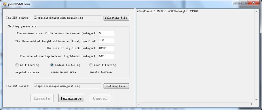
In the section
of “The DSM source”, the DSM before interpolation from the previous step is
selected, and in the section of “The DSM result”, the filename of resultant
DSM, which will be the outcome of this step of post processing, is set.
After the
interface is launched, the default values for these parameters are given. In
most cases, the default values can be used. The blank area of the right side
will display the information printed by the command program. The meaning of
parameters is as follows:
The maximum
size of the errors to remove: the size of the area of maximum errors to remove.
The number, 5, indicates that outliers up to the size of 5 x 5 can be removed.
The parameter is integer.
The threshold
of height difference: The point (or small areas) where height difference beyond
the surroundings is above the threshold is deemed as outliers. The parameter is
float and unit is meter.
The size of big
block: the size of big block which is used to divide the image. The DSM is so
large that block division is required. The parameter is integer.
The size of
overlap between big-blocks: the size of overlap between the adjacent big-blocks. The
parameter is integer.
According to
the features of the terrain of covered area, a filtering method for
post-processing is selected among no filtering (suitable for vegetation area),
median filtering (suitable for dense urban area), and mean filtering (suitable
for smooth terrain). In this sample, median filtering is selected.
Again, still by
the manner of visual checking, if on the interpolated DSM after post processing
small areas of errors is still found, the interactive tool for editing DSM/DEM
(i.e., collectPolygons.exe)
is continually used for editing. After editing, users can determine if post
processing for DSM is required again in the light of their needs. For more
details, please refer to “Usage of the collectPolygons.exe program”.
Step 3: Automatic true ortho-rectification
Clicking the
icon showing “True Ortho” in the main interface,
The following
menu will pop up.
The command item, Aerial Ortho, in the above menu is to
call the function of ortho-rectification. After
processing, an ortho-mosaicked
image is generated. The operating interface is as follows:
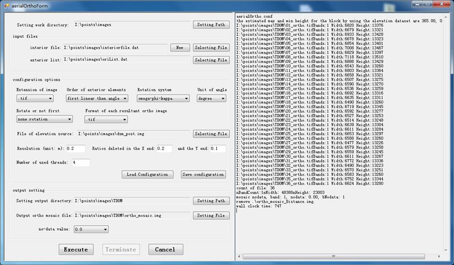
The concept of
work directory is the same as that in stereo matching and DSM generation. All
files required in the course of ortho-rectification
should be put in the work directory. In the section of input files in this
interface, the file of interior parameters of camera and the list file
of exterior elements are the same as those in the step of stereo
matching and DSM generation. Thus, the directory, I:\points\images, is
still set as the work directory in this step.
All options
before the option, Format of each resultant ortho
image, are the same as those in the step of stereo matching and DSM generation.
Format of each resultant ortho image: the file format
can be configured. The formats, such as GTiff and
ERDAS IMAGINE (.img), can be used.
File of
elevation source: the full file path of the external elevation source used in
the ortho-rectification. The result in Step 2, post
processing for DSM, is selected as the elevation source. The coordinate system
of elevation file must be the same as that of exterior elements and the
elevation file covers all the areas of these images. If third party elevation
source is used, please make sure the sameness of coordinate system. Resolution:
the image resolution (Unit: m) of the ortho-rectified
image. The resolution of ortho-rectified image can not be better than the actual GSD (ground spacing
distance). Ratios deleted in the X end and the Y end: the ratios need to be
deleted in the two ends for X, Y directions, respectively. The remained center
part of ortho-rectified image after deleted in ends
is a portion with high quality.
Number of used
threads: setting the number of used threads (CPU cores or the virtual CPU cores
by using hyper-threading technology). For the cases where CPU cores are enough,
we suggest that number of 4, 6 or 8 is set here.
After the above
options in the interface are set, users can click “Save Configuration” to save
these options. These configuration options will be saved in a configuration
file, aerialOrtho.conf, and next time the options can
be loaded from the configuration file by clicking “Load Configuration”. The
configuration file, aerialOrtho.conf, is also stored
in the work directory. If the button of “Execute” is clicked, the configuration
file will also be generated in the same way.
In the output
setting, users should set the output directory and the filename of the ortho-mosaicked image. In the output directory, the ortho-rectified image for each image will be stored. The
resultant images after ortho-rectification are named
in a specific rule: image ID_ortho.extension. The
data type of ortho-rectified images, as well as the
number of bands, is the same as that of original images, e.g., unsigned 8 for
original image, still unsigned 8 for ortho-rectified
image. The file format of resultant images is set in the configuration option “Format
of each resultant ortho image”. The output ortho-mosaicked image should also be stored in the output
directory.
No-data value
in the output setting is the value used to fill in the area without intensity
value (area with no-data value) in the resultant ortho-image.
The value is also called as invalid value or background value.
After finishing
the setting of configuration options, input and output setting, users can click
the button of “Execute”. The called program, aerialOrtho.exe, starts to run and
the required time to finish the whole procedure is different according to the
size of the aerial block. In the course of computation, the buttons of
“Execute” and “Cancel” on the bottom of the form is invalid. The two buttons can not be clicked in case they are clicked many times in
the course of running. Users can learn the progress and the running status via
the re-directed output printing (sometime printing may delay) on the right
side. User can also check the information of resources (CPU, memory and Disks)
possessed by the program from Task Manager and Resource Monitor of Windows OS.
Once the execution of aerialOrtho.exe is finished, a message box will pop up
showing that the processing is closed successfully or terminated (aborted).
After clicking OK button on the message box, the GUI program returns to the
available status. Users can either click the button of “Cancel” on the bottom
or click the closing icon on the up-right corner of the interface to close this
GUI program. Or users can select and set new input and output to fulfill a new
task.
User can click
the button of “Terminate” on the bottom if they need to abort the processing
(not the closing of GUI form). The GUI program, aerialOrthoForm.exe, will kill
the process of aerialOrtho.exe which is being called. Killing the process of
aerialOrtho.exe may delay (less than one second or several seconds). Once the process
is killed, a message box will pop up showing that the processing is terminated
(aborted) or closed successfully. After clicking OK button on the message box,
the GUI program returns to the available status. Users can either click the
button of “Cancel” on the bottom or click the closing icon on the up-right
corner of the interface to close this GUI program. Or users can select and set
new input and output to fulfill a new task.
Attention: the
button of “Cancel” on the bottom is only for closing the GUI program. If the
called logical program (i.e., aerialOrtho.exe) is running, users should first
click the button of “Terminate” to abort the processing task or wait until the
processing task is finished, and then close the GUI program. Users can not click
the button of “Cancel” or click the closing icon on the up-right corner of the
interface to close this GUI program when the called logical program is running.
The blank area
of the right side will display the information printed by the command program,
and the printed information will also be saved in a log file named as aerialOrtho_ddMMMyyyyHHmmss_log.txt.
In the filename, dd are two digital numbers
indicating a date, MMM are three English characters indicating an abbreviation
of a month, yyyy are four digital numbers indicating
a year, and HHmmss are digital numbers indicating
hour, minute and second in the form of 24 hours. The log file is also stored in
the work directory.
All configuration
options are saved in the configuration file, aerialOrtho.conf,
through a certain type of form in the course of running of program. The
configuration file can be used in the action of loading configuration.
At the same
time, a list file named ortho_List.txt is generated, which is saved in the
output directory. The list file includes, in sequence, all filenames of ortho-rectified images whose order is the same as that in
the list of exterior elements of images. The format of the list is as follows:
I:\points\images\TDOM\01_ortho.tif
I:\points\images\TDOM\02_ortho.tif
I:\points\images\TDOM\03_ortho.tif
I:\points\images\TDOM\04_ortho.tif
I:\points\images\TDOM\05_ortho.tif
I:\points\images\TDOM\06_ortho.tif
….
Step 4: Comparing surface height
and change finding
By comparing
DSMs of two different phases, the program can automatically find change of the
surface height and calculate the value of changed height. Clicking
the icon showing “Surface Change” in the main interface,
The operating
interface of change of surface height is launched.

The
corresponding DSM files are selected in the sections of the previous DSM and
the next DSM, respectively. After processing, the file of height difference is
obtained. Users can set two parameters, the height threshold and no-data value.
The height threshold:
If the height difference is less than the threshold, the difference is not
interesting and it will be assigned as no-data value in the resultant file. For
the case where the height difference is more than the threshold, the real
difference will saved in the resultant file.
No-data: no-data
is the value used to fill in the area without change of surface height (or
invalid area) in the resultant file. No-data can be determined either from
input DSM or from the right side list box.
Step 5: Automatic DSM2DTM
Clicking the icon showing “DSM
to DTM” in the main interface,
The operating
interface of automatic DSM2DTM is launched.

The program
adopts an algorithm with multilevel triangle-based ground filtering. It deletes
the non-grounded objects like buildings, trees in DSM and transforms the DSM to
DTM where the pure ground height is saved. The input file is DSM source and the
output file is resultant DTM.
The meaning of
parameters is as follows:
The predefined size: the defined size in which the lowest point is
selected as a ground point; unit: the same as the grid spacing (cell size),
e.g., 40.0. It means that the lowest point in a grid, whose sizes of width and
height are both 40 meters (assuming the unit of grid spacing is meter), is
taken as a ground point. The higher is the predefined size, the more levels in
the pyramids are generated. Level number of pyramids decrease, then the built triangles
is to be dense. This parameter is usually decided by the size of the biggest
non-ground object in the terrain area. If the predefined size is less than the
size of non-ground object, these objects will not be filtered out. On the
contrary, if the predefined size is too large to maintain some terrain details.
Thus, users need find a balance between filtering out big non-ground objects
and maintaining the terrain details in the light of the requirements of
applications.
Level, to which level the DSM is filtered. The higher is the level set,
the less ground points are generated, the less terrain details remain, and the
more efficient is the processing. The lower is the level set, the more ground
points are generated, the more terrain details remain, and the less efficient
is the processing. Usually the triangulation of mass points and searching a
specific triangle in a huge triangulation is inefficient. The level set can not be higher than (the highest level - 1), level is
0-based, e.g., 3.
The threshold
of distance: the threshold of distance from
a point to the corresponding triangle. In the course of filtering, a point
whose distance to its corresponding triangle is more than the threshold is
deemed as a non-ground point, vice versa, e.g., 1.0 meter. If the value of
threshold is low, there are less ground points which will survive in the
filtering processing and there are also some risks that the true ground point
may be filtered out by taking them as non-ground points.
The size of
block: for processing large raster, block division is needed. Filtering is
fulfilled, block by block, and its size must bigger than two times of
overlapping size, e.g., 6144. Usually the default value is used. The reason
that block division is used is that a large DSM will result in huge ground
points which require huge computation for the filtering processing. The block
division is a way which promotes computational efficiency and saves memory
consumption.
The size of
overlap between blocks: the size of overlap between the adjacent blocks, e.g.
128. The overlay ensures the rightness of border of each block. Usually the
default value is used.
No-data:
no-data is the value used to fill in the area without height value. Because
each grid in raster file must be assigned a value, for some cases where there
are no real height values in some areas, the concept of no-data is introduced.
No-data can be determined either from input DSM or from the right side list box
in this interface.
If there are
some non-ground objects which are not
filtered out, such as buildings and vegetation areas, or small areas of errors
in the resultant DTM in this step, the interactive tool for editing DSM/DEM
(i.e., collectPolygons.exe)
can be used for editing. For more details, please refer to “Usage of the
collectPolygons.exe program”.
Step 6: Height estimation of building
/ tree
Clicking the icon showing “Building
height” in the main interface,
The operating interface of height estimation of building / tree
is launched.

The
corresponding files are selected in the sections of the ground height (DTM) and
the surface height (DSM), respectively. After processing, the file of building
/ tree height is obtained. Users can set two parameters, the height threshold
and no-data value.
The height
threshold: the height being less than the threshold is the value which is not
interesting or the possible existing errors. The value will be replaced by
no-data in the file of building / tree height. The height being more than the
threshold is an interesting and reliable value, which as a true value will be
saved in the file of building / tree height.
No-data:
no-data is the value used to fill in the area without building / tree (or
invalid area) in the resultant file. No-data can be determined either from
input DSM or from the right side list box.
Step 7: Applications
Clicking the icon showing “App”
in the main interface,
The following
menu will pop up.
Currently two applications modules are included, i.e.,
volume calculation and automatic extraction of building
attributes in the light of buildings footprints.
Volume
calculation: a polygon in the vector form in which volume is calculated and
highly dense DSM are given, the module estimates the volume of objects (e.g.,
sands, small stones, coal, mineral particles and garbage) occupying the area.
For more details, please refer to “Usage of the calVolume.exe and
calVolumeForm.exe programs”. Users can click the command item, Polygons Drawing
Tool, in above menu to launch the interactive tool, collectPolygons.exe, to
collect the polygon and save it.
Automatic
extraction of building attributes: a vector file with ERSI shape format, which
including multiple polygons of building footprint, and the corresponding nDSM dataset are given, the module automatically extracts
the center position (x, y coordinates) of building, area of ground, height of
building, number of layers, and construction area of building for each
building. Moreover, these extracted values are set as new attributes for these
polygons. nDSM can either be
obtained by subtracting DTM from DSM in the module of buildingHeightForm.exe,
or be obtained by calculating difference between two DSMs in the module of
surfaceChangeForm.exe. The former can be used to extract building height from
the bottom to top, number of layers, etc., while the latter can be used to
automatically find new, illegal, added, demolished, or height-exceeded
buildings and extract their attributes, such as position, height, layers, ground
area, and construction area of these found buildings. For more details, please
refer to “Usage of the extBldgAttributes.exe and extBldgAttributesForm.exe
programs”. Users can click the command item, Polygons Drawing Tool, in above
menu to launch the interactive tool, collectPolygons.exe, to collect polygons
on nDSM and save them to a vector file. Polygons of building
footprint in vector file can also be from third party source. For both cases,
it is required that building footprints are accurately aligned with the actual
boundaries of buildings. And, the vector file including polygons and the nDSM file should be geo-coded and the underlying coordinate
system is the same.
Step 8: 3D modeling with true color textures
Clicking the icon showing “Textured 3D Model”
in the main interface,
The following
menu will pop up.
By clicking the command item, textured 3D modeling, the
GUI program is launched as follows:
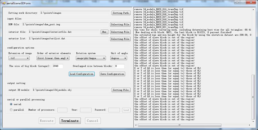
All files required in the course of generation of 3D
models should be put in the same directory and the directory is set as work
directory. The required files are DSM file, image files used for texture
mapping, the file of interior parameters of camera, and the list file of
exterior elements in an aerial block. Users should copy all these files to a
directory and set it as work directory.
The image file used for texture mapping in the work
directory is associated with the image filename via the image ID in the list
file of exterior elements. Image ID plus extension is the name of image file. The
data type of the images which are used for texture mapping is unsigned 8 bit
integer. If it is not, user should stretch the images to unsigned 8 bit using
the autoStretch.exe program provided by MASI software (the command item,
automatically stretch image to 8 bit, in the above menu to call the function).
In the input
files, users should select the DSM file and the list file of exterior elements.
Then, users can set configuration options and other setting. For the meaning of
configuration options and operating method, please refer to “Usage of the aerialScene3D.exe and aerialScene3DForm.exe programs”.
Hereto, the
whole flowchart for aerial images is finished, including automatic stereo matching
and generation of highly dense DSM, automatic 3D
modeling with true
color textures, automatic (true) ortho-rectification,
automatic finding change of surface height, automatically transforming DSM to
DTM, height estimation of building / tree,
volume calculation, extraction of building attributes, etc. If the functions,
such as image displaying, interactive editing of DSM/DEM, collecting
polygons, automatic
mosaic (mosaic of DSMs, mosaic of ortho-rectified
images, mosaic of histogram matched images), transforming
RGB image to grey image, rotation of image, reflection of image, transforming
point clouds to surface in the form of raster, transforming DSM with raster
form to point clouds, image cropping, and creating overviews for image, are
needed, please refer to user manual of the software.